Boilerplate Spec

Single Wall Mounted Hood System
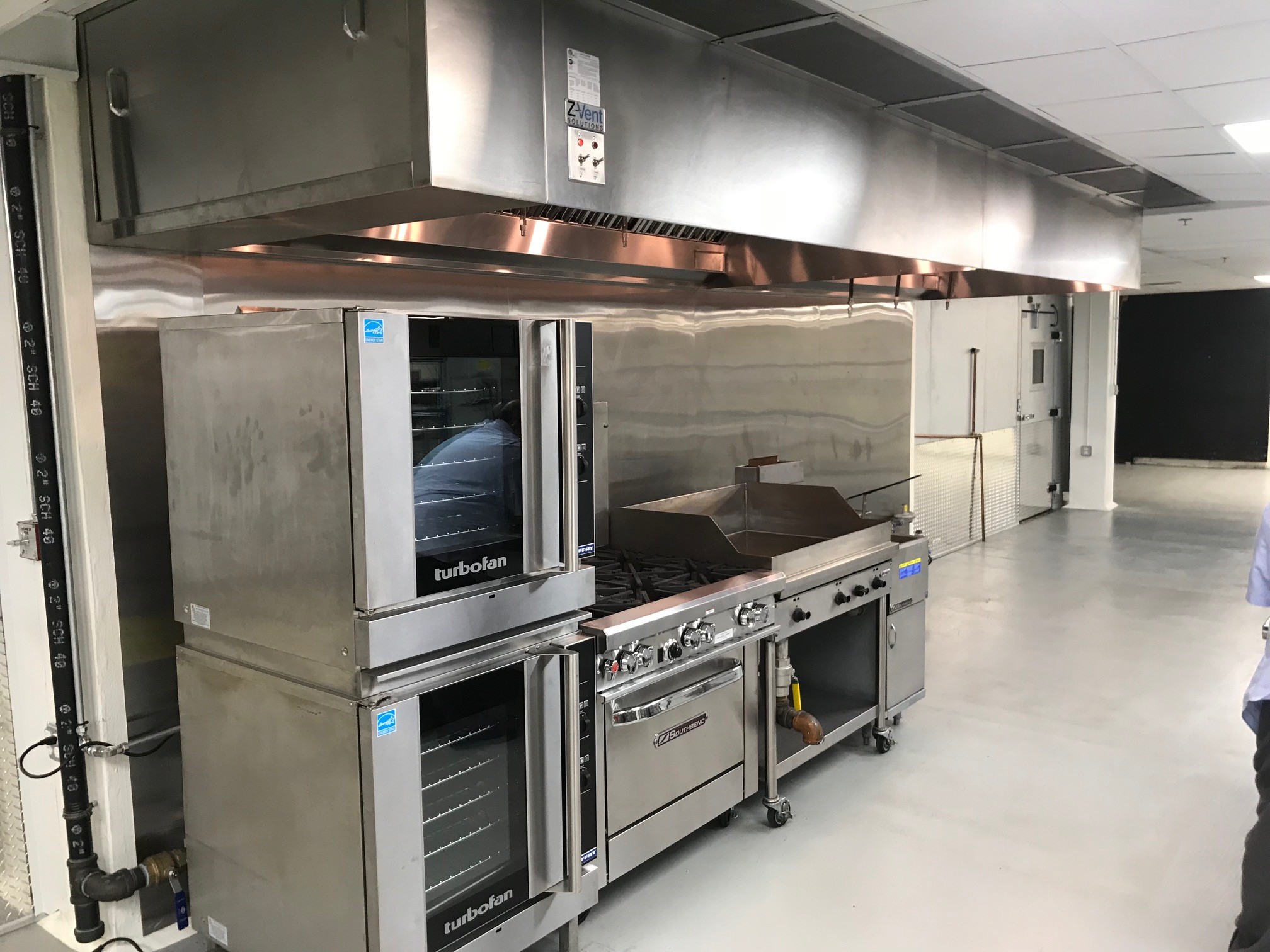
EXHAUST HOOD PER ATTACHED DRAWING: One (1) Model ND2 series is a Type I, wall canopy hood ETL listed for use over 450°F/600°F/700°F cooking surface temperatures. Insulated, double-wall rigid front has aerodynamic design ZVS-ND-2PSP “mechanical baffle” on the front of the hood’s capture area. 3” rear stand-off to meet NFPA 96 requirements. Mounting brackets on all (4) four corners of the canopy as well as additional mounting brackets as required. Polished 430 stainless steel on the interior and exterior. Fully welded and polished front corners. Furnish stainless steel trim to ceiling which matches hood finish as required by project conditions. Removable stainless steel baffle filters with deep grease trough and a removable grease cup. UL Listed, pre-wired, incandescent light fixtures and tempered glass globes, and 100-watt bulb. Listed light and fan control switches flush mounted and prewired to top canopy mounted junction box. Furnished with prewired heat sensors factory set to 120 degrees F and secondary room sensor. See drawings for location.
UTILITY CABINET: One (1) stainless steel utility cabinet mounted on the end of the exhaust canopy. Polished stainless-steel exterior to match exhaust hood to contain fire protection tank and prewired control for hood lights and fan controls. Furnished with removable panel with flush mounted latches for service and inspection access. See drawings for left or right mounting location.
OR
REMOTE UTILITY CABINET: One (1) stainless steel utility cabinet remote wall mounted. Polished stainless-steel exterior to match exhaust hood to contain fire protection system tank. Furnished with removable panel with flush mounted latches for service and inspection access. See drawings for location.
FIRE PROTECTION SYSTEM: One (1) Ansul Model R-102, U.L. 300 Listed, liquid agent type. System to provide hood, duct, plenum and required surface protection. Exposed piping to be stainless steel. Mount system as shown on the drawings. Furnish (1) dual micro switch with system and furnish (1) mechanical gas valve (to be installed by Mechanical Contractor).
MAKE-UP AIR PLENUM: One (1) top mounted make-up air plenum. Polished stainless-steel exterior to match exhaust hood. Stainless steel interior baffles and perforated bottom diffuser for even gentle air distribution.
END PANELS: 18 gauge Stainless-steel end panels which match hood finish as required by project conditions.
CLUSURE PANELS: 18 gauge Stainless-steel end panels which match hood finish from top of hood to 2” above finished ceiling as required by project conditions.
CONTROLS: One (1) DCV prewired, control panel flush mounted in utility cabinet. Control to have digital interface with LCD screen, customizable microprocessor, plug and play wiring between digital interface and equipment, automatic fan operation – meets IMC Code 507.1.1, alarm notifications, integrated reset for electric gas valves and monitoring of fan overload trips. See drawings for location.
OR
REMOTE CONTROLS: One (1) DCV prewired, control panel for flush mount in wall or utility distribution system. Control to have digital interface with LCD screen, customizable microprocessor, automatic fan operation – meets IMC Code 507.1.1, alarm notifications, integrated reset for electric gas valves, monitoring of fan overload trips and 30’ plug and play wiring between digital interface and equipment.
EXHAUST FAN: One (1) ZVS-DU-HFA Spun aluminum, roof or wall mounted, direct drive, upblast centrifugal exhaust ventilator. ETL Listed and comply with UL705 (electrical) standards, ETL Listed and comply with UL762 and ULC-S645 Standards. Fan shall bear the AMCA certified ratings seal for sound and air performance. Fan to include grease containment box, curb hinges, 20” high insulated roof curb, and disconnect switch.
OR
EXHAUST FAN: One (1) ZVS-USBI-RM Utility set, direct drive, directional centrifugal exhaust ventilator. ETL Listed and complies with UL762 and ULC-S645 Standards. The fan wheel shall be centrifugal backward inclined and non-overloading. Wheels shall be balanced in two planes and done in accordance with AMCA standard 204-96, Balance Quality and Vibration Levels for Fans. Fan to include utility set grease cup, heavy galvanized steel base with mounting holes, 14” high support rails and disconnect switch.
MAKE-UP AIR FURNACE UNIT: One (1) ZVS-MPU Roof top mounted make-up air unit with gas fired furnace. The fan shall be constructed of heavy gauge G90 galvanized steel. Doors are removable for easy access to interior components for service. Large intake area to assure low pressure drop and maximum weather resistance with 2″ washable filters. Base constructed of galvanized steel and structurally reinforced to accommodate the blower assembly. Direct drive blower assembly controlled by a variable frequency drive. Motors shall be heavy duty ball bearing type and furnished at the specified voltage, phase and enclosure. Fan shall be listed by ETL and conforms to UL705 and CSA Std. C22.2, No. 113 standards.
OR
MAKE-UP AIR HEAT & COOLING UNIT: One (1) ZVS-MPU-DX Roof top mounted make-up air unit with gasfired furnace and DX cooling. The fan shall be constructed of heavy gauge G90 galvanized steel. Doors are removable for easy access to interior components for service. Large intake area to assure low pressure drop and maximum weather resistance with 2″ washable filters. Base constructed of galvanized steel and structurally reinforced to accommodate the blower assembly. Direct drive blower assembly controlled by a variable frequency drive. Motors shall be heavy duty ball bearing type and furnished at the specified voltage, phase and enclosure. Fan shall be listed by ETL and conforms to UL705 and CSA Std. C22.2, No. 113 standards.
ROOF CURBS AND EQUIPMENT SUPPORT RAIL: Curb 18 gauge, all welded galvanized construction. Curbs to be internally insulated with rigid fiberglass with foil backing. Equipment support rail to be same construction and material as curb with adjustable cap for leveling in the field.
EXHAUST DUCT: Furnish and install double wall, insulated continuous grease rated ductwork from exhaust hood to exhaust fan complete with all mounting and hanging hardware. Intended for use with Type I exhaust hoods. Inner duct section shall be constructed of .036″ thick, 430 type stainless steel. Outer Duct section wall shall be constructed of 430 stainless steel at a minimum of .024″ thickness. Duct shall include 2 layers of Super Wool 607 Plus or Insulfrax Elite Blanket between the inner and outer wall insulation between the inner and outer wall. Duct sections shall be held together by the means of a formed V clamp. Duct joints shall be sealed with 3M Fire Barrier 2000+. Duct wall assembly shall be tested and listed at 3/4″ or zero-inch clearance, according to classifications. Furnish clean-outs, quantity and locations as required and shown on drawings.
OR
EXHAUST DUCT: Exhaust duct to be 16 gauge black iron material. All seams to have continuous liquid-tight external welds. With (2) layers of fire rated duct wrap (as required). Furnish clean-outs, quantity and locations as required and shown on drawings.
MAKE-UP AIR DUCT: Furnish and install 22 gauge steel continuous ductwork from make-up air plenum to make-up air unit complete with all mounting and hanging hardware. Make up air duct fabricated per SMACNA low pressure standards per drawings.
OR
MAKE-UP AIR DUCT: Furnish and install 22 gauge steel continuous ductwork with 1” R-13 internal rigid insulation from make-up air plenum to make-up air unit complete with all mounting and hanging hardware. Make up air duct fabricated per SMACNA low pressure standards.
INSTALLATION: Furnish and install complete turn-key system. Which includes delivery and hanging hoods, setting fans and furnace, location of roof curbs and equipment support rails as shown on shop drawings. Fabricating and installing exhaust and make-up air ductwork complete with balancing dampers as required. Fabricating and installing make up air plenum. Fabricating and installing all end panels to ceiling, closure panels and trim as required. Furnish and install all stainless steel wall panels as required. Furnish, install and certify fire suppression system, furnish shop drawings for approval to authorities and obtain state and local approval. Entire system start-up, balance and inspected by factory authorized technician upon completion of installation.
EXHAUST SYSTEM WORK BY OTHER TRADES:
GENERAL CONTRACTOR: Provide and install (if required) fire rated exhaust duct enclosures with cleanout access panels and/or fire rated liners wherever exhaust ducts are within 18″ of a combustible surface to reduce clearance between duct and combustibles to 3″ per 675 IAC 18-1.2-124 Section 2013.
ROOFING CONTRACTOR: Provide roof deck openings. Set in place and flash (if required) roof curbs and equipment support rail furnished by the hood system manufacturer.
STRUCTURAL CONTRACTOR: Frame roof curb openings as required. Coordinate joist or structural member installation to provide required clearances for ductwork and shaft assemblies.
ELECTRICAL CONTRACTOR: Provide 120/60/1 20 amp circuit, for hood lights and controls to junction box on top of hood. Provide 3 phase circuit (for fan motors) to disconnect switch mounted on exterior of supply fan cabinet. Extend power wiring from motor starter panel (mounted on exterior of supply fan) to connection point on exhaust fans. Provide conduit and four wires from terminal block on hood to terminal block on supply fan motor starter panel. Provide 120 volt control circuit through the heat switch to the furnace. Provide conduit and two wires from terminal block on hood to micro-switch of fire protection system. Interlock wiring of the supply fans motor control device through the fire system micro switch, shutting off supply air in the event of fire system actuation. Furnish and install an octagon box for the fire system pull station, mounting the centerline of the box at 54″ above the finished floor. Run 1/2″ conduit from the top of the box to 6″ above the ceiling. Pull station to be furnished with fire system. Furnish and install automatic power shut off devices (shunt trip breakers, or definite purpose contactors) with interlock to fire system micro switch, shutting off all power below the hood (including control voltage) in the event of fire system actuation. This work must be in accordance with N.F.P.A. 17A, I.M.C. Chapter 20, and the N.E.C.
MECHANICAL CONTRACTOR: Provide net room air demand as indicated on the hood system drawings. This air volume is required only when hood system is in operation. Provide normal heating and cooling of the kitchen area. Install gas valve (supplied with the fire suppression system) in the main supply line serving the cooking equipment to shut off gas service to the cooking equipment in the event of fire system actuation. Provide and install service to gas fired furnace on building roof.

